2168
G.Z. Yang et al. / Energy Conversion and Management 47 (2006) 2167–2177
cooling output of 10.30 kW and a COP of 0.34 could be obtained with a hot water inlet temperature of 85 ꢀC,
a cooling water inlet temperature of 30 ꢀC and a chilled water inlet temperature of 14 ꢀC [4]. No mass recovery
process was included in the chiller.
The silica gel–water adsorption refrigeration system has been investigated systematically by Saha [5–9]. To
utilize low grade waste heat, Saha et al. introduced a three stage adsorption cycle that could be driven by waste
heat of 50 ꢀC in combination with a heat sink of 30 ꢀC [6]. Though the cooling output and COP are not so
exciting, considering that the driving energy comes from waste heat, the cycle is worthy of further study. Saha
et al. built a two stage non-regenerative adsorption chiller that could be operated effectively with 55 ꢀC solar
energy/waste heat in combination with a 30 ꢀC coolant inlet temperature [7].
For a conventional two bed continuous cycle, the highly dynamic adsorption rate results in fluctuations of
the cooling output and the cooling load of the condenser. The cooling output fluctuation, which will result in
fluctuation of the chilled water outlet temperature, is not welcome in some occasions. When a cooling tower is
used to supply the cooling water, the fluctuation of the cooling load of the condenser will cause variation of
the cooling water inlet temperature. To improve the conditions, a multi-bed adsorption refrigeration cycle has
been introduced and investigated [8,9]. At any time, there is more than one adsorber undergoing the adsorp-
tion (desorption) phase, and thus, the cooling load of the condenser and the heating load of the evaporator
can be adjusted automatically. Thus, the rapid increase (decrease) of the loads can be avoided. Besides, Saha
et al. also introduced a dual mode, multi-stage, multi-bed regenerative adsorption system [10]. The system
operates in the multi-stage, two bed mode when the hot water inlet temperature is less than 60 ꢀC and in
the single stage, multi-bed mode when higher hot water inlet temperature can be obtained.
Heat and mass recoveries can improve the performance of an adsorption system effectively. R.Z. Wang has
thoroughly investigated the influences of heat and mass recoveries on the performance of adsorption systems
and has also performed comparisons with conventional adsorption cycles [11]. The influences of the degrees of
heat and mass recoveries on adsorption system performance have been studied by Wang [12].
An adsorption heat pump system with heat recovery was studied by Wu et al. [13] in which a novel shell-
tube exchanger structure was adopted as the adsorption heat exchanger. Gui et al. conducted experimental
researches on the dynamic characteristics of a heat regenerative adsorption air conditioning system [14]. To
increase the cooling output, Alam et al. introduced a mass recovery process into a four bed adsorption cycle
[15]. It was shown that the cooling output of the system was higher than that of a two stage system for regen-
eration temperatures higher than 70 ꢀC.
During the past several years, the research group of R.Z. Wang has systematically studied various adsorp-
tion refrigeration cycles with heat and mass recoveries and built some adsorption chiller prototypes [16].
In comparison with absorption refrigeration, adsorption refrigeration systems have the superiority in the
smaller cooling capacity range (for example, 6100 kW). There are already a lot of researches and products
of silica gel–water adsorption chillers, however, no scale of 1 kW has been studied. In this paper, a compact
adsorption room air conditioner with a cooling capacity of 1 kW is designed and fabricated, and experimental
researches are also conducted. To use low temperature driving energy, silica gel and water are chosen as the
adsorption pair.
2. Design of the prototype
For traditional two bed adsorption refrigeration systems, there is always a vacuum valve between the
adsorber and condenser (evaporator). The valve between the adsorber and condenser is opened when the pres-
sure in the adsorber increases to that in the condenser at the beginning of the desorption process and closed at
the end of the desorption process. Similarly, the valve between the adsorber and evaporator is opened when
the pressure in the adsorber decreases to that in the evaporator at the beginning of the adsorption process and
closed at the end of the adsorption process. For a real adsorption refrigeration system, the time interval of one
cycle is usually in several tens of minutes. Thus, the vacuum valves must be opened and closed frequently. So,
they are often damaged, which reduces the reliability of adsorption refrigeration systems.
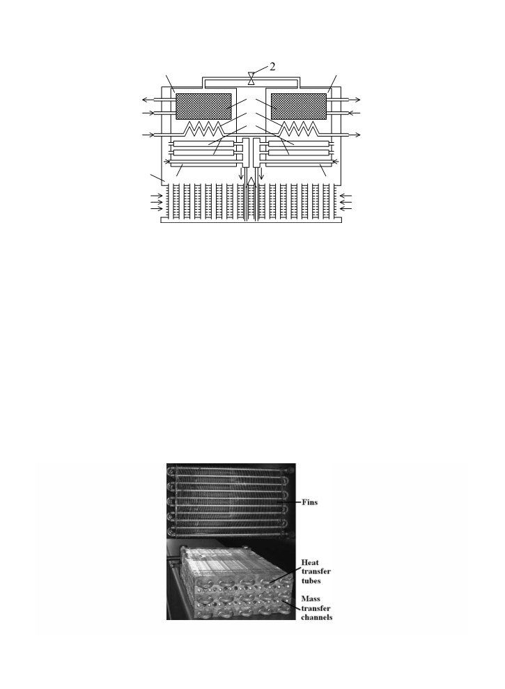
For the adsorption air conditioner proposed in this paper (Fig. 1), we think the reliability is vitally important.
Therefore, in our design, we enclose one adsorber, one water condenser and one water evaporator (located from
the upper to lower) in one vacuum chamber (adsorption/desorption working chamber), and then, no vacuum

 Yang, Xiaoyin